Chemically Rigidized Expandable Structures
M.C. Bernasconi Consultants
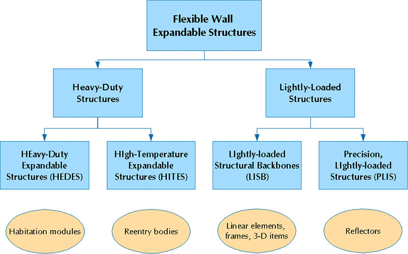
Dr. Marco C. Bernasconi, in particular because of his long involvement with the developments at Contraves Space, possesses of a unique expertise in the field of inflatable, chemically-rigidized expandable structures for space applications (called herein CRES, for short). For historical reasons, work at Contraves centered on microwave antenna reflectors, as exemplified by the realization of the first "inflatable" offset reflector; however, work has been done in all classes of flexible-wall expandable structures (a superset of CRES -- see diagram below) with the exception of the "high- temperature" one.
At a higher degree of detail, a second level of analysis lies within the lightweight-backbones field. In the current, early application phase of the technology, one would seem well advised to select with care both morphology of the structure and type of application, looking for simplicity and design margins that help to make the product highly resilient to anomalies. External needs and the technology's versatility combine to produce a vast range of prospective uses, nonetheless.
Backbone structures can be classified
We summarize below the activities for applications in the three different classes: precision structures, backbones, and (normal temperature) heavy-duty items.
Precision Structures
Reflectors for Communications Antennae
Under ESTEC sponsorship, in addition to a number of minor technological objects, the experimental activities at Contraves used objects with sizes ranging from 1- to 10-m aperture. Three 1/10-scale models of a symmetric (center-fed) reflector were used in parallel with the materials technology development effort to appraise issues such as folding and deployment, manufacture processes, and achievable accuracy.
In successive phases, three 2.8-m projected-aperture reflectors (designed for operation at 3.6 GHz) allowed the execution of following tests:
- accuracy needed for operation at the frequency of interest -- the improved manufacturing procedures adopted during that development phase allowed a reduction of the rms error from 0.9 mm error (for the object measured electrically) to 0.7 mm (for the last object manufactured), while identifying the sources of the main remaining inaccuracies;
- high packaging efficiency -- the packaging efficiency figures were verified using the object that was successively subjected to electrical measurements; no degradation of surface quality was determined as consequence of the folding and deployment exercises;
- controlled deployment in vacuo -- a vacuum deployment test demonstrated the quality of the residual air control procedures, the correctness of the deployment sequence (Figure 1), and the controlled deployment of the structure;
- the required electrical performance -- electrical measurements were performed on the first complete object (Figure 2a), after it had undergone the full cycle of pressurization tests, folding, packaging, deployment, and cure;
- cure under (simulated) space conditions -- a TVC solar simulation test (Figure 2b) demonstrated the correctness of the reflector's thermal design.
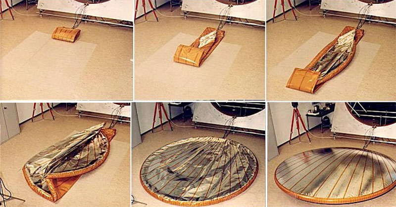
Figure 1: A typical deployment sequence of an inflatable offset reflector demonstrated with "LOAD-3-1" -- the first ever rigidizable offset reflector (on the floor of Contraves' 10'000-class clean room) (Contraves pictures).
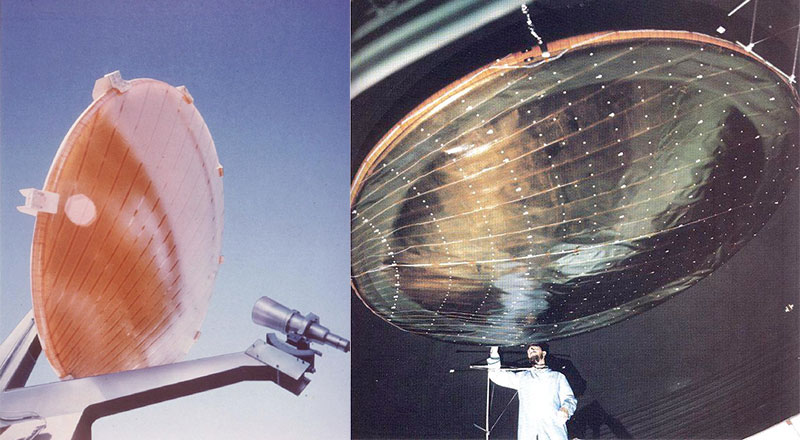
Figure 2: (left) The 3-m ISRS offset antenna as used for far-field RF measurements, with feeds and support structure by CSELT, Turin (CSELT picture). Fig 3: (right) "LOAD-3-3" ISRS offset reflector suspended under the lid of the ESTEC HBF3 in preparation for its thermal-vacuum cure test (ESTEC picture).
Successively, a 10-m aperture, offset-fed reflector designed for multi-beam operation at 1.6 GHz was manufactured and tested (under clean-room conditions -- Figure 3): with an initial 2.15-mm rms error, after the folding and deployment cycle, this reflector exhibited a surface error of 2.66 mm rms (0.88 mm rms over the central quarter of the aperture), yielding a gain of 42.6 dBi and a sidelobe level of -33.8 dB. In addition to the experimental activities, we provided contributions and assessments for projects like the Canadian M-Sat and the ESA PSDE SAT-2/ARTEMIS L-band reflectors.
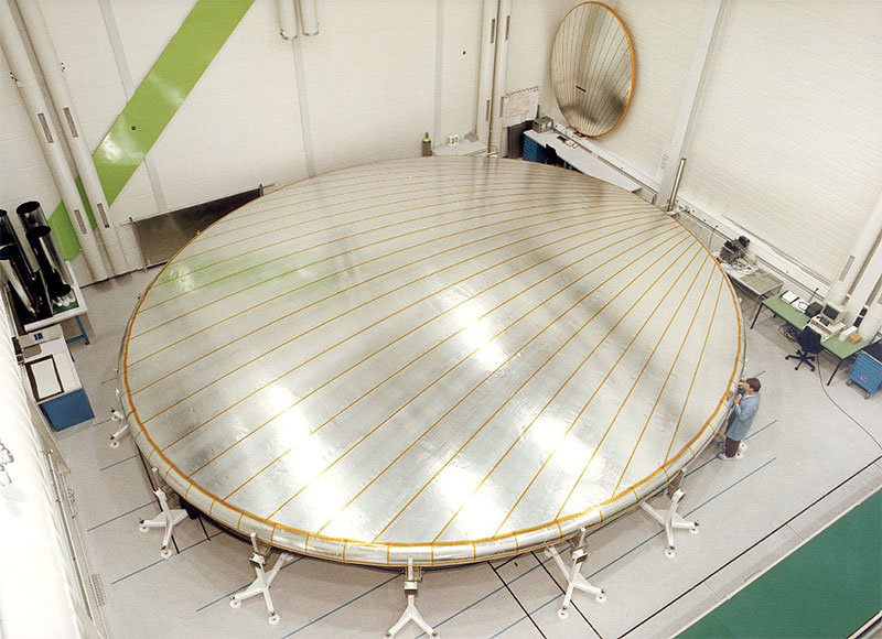
Figure 3: The LOAD-10 offset reflector at the end of manufacture (Contraves picture).
QUASAT & Radio Telescope Reflectors
While most antennae for communications purposes use an offset-fed configuration, symmetric (on-axis) reflectors serve well the applications in radio astronomy, where issues of gain and resolution predominate. When investigating the QUASAT orbital radio telescope element, the European scientific group suggested to have recourse to a CRES reflector (Figure 4). Three supporting activities followed at Contraves, culminating in the manufacture and test (under clean-room conditions) of a 5.7m diameter (scaled) Test Article (Figure 5), that achieved an initial surface accuracy of 1.23-mm rms.
In addition, we provided contributions and assessments for scientific projects, among them: the QUASAT system Phase A effort, the (somewhat similar) IKI Radioastron VLBI element, as well as various center-fed reflectors for lightsat applications, including the MODEST project. From this work evolved a concept for a completely self-supporting reflector concept that is mounted as a cantilevered element on the central body of a spacecraft. This seems particularly well-suited for lightsats, to which it can provide relatively large apertures (up to 6 m) with quite compact stowage volumes.
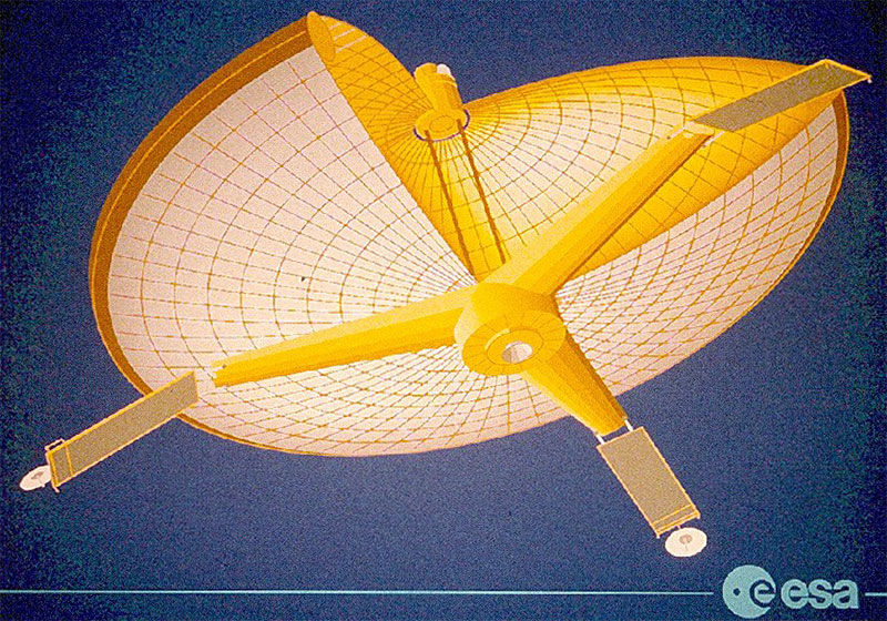
Figure 4: An early "artistic impression" of the QUASAT satellite (ESA picture)
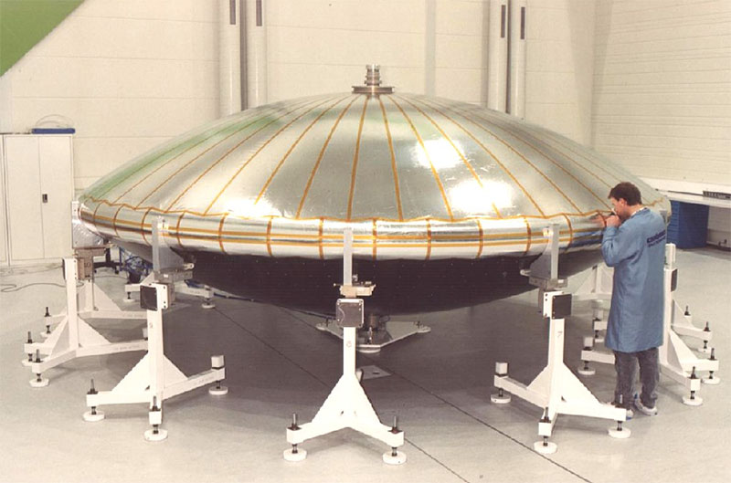
Figure 5: The 6-m Test Article for the QUASAT radio telescope reflector (nominally at 1/3 scale) within Contraves Space 100,000-class clean room.
Solar Concentrators
Solar collector with high concentration ratio have long represented a preeminent application for flexible-wall structures, both of the rigidized and of the inflatable kind. The study of a Solar-Thermal Upper Stage, led by EADS Space Transportation, offered us the opportunity to assess the interest of continuously-inflated reflectors for such an application. The prescribed short life time of the system (up to a month) makes the employment to this type of technology possible.
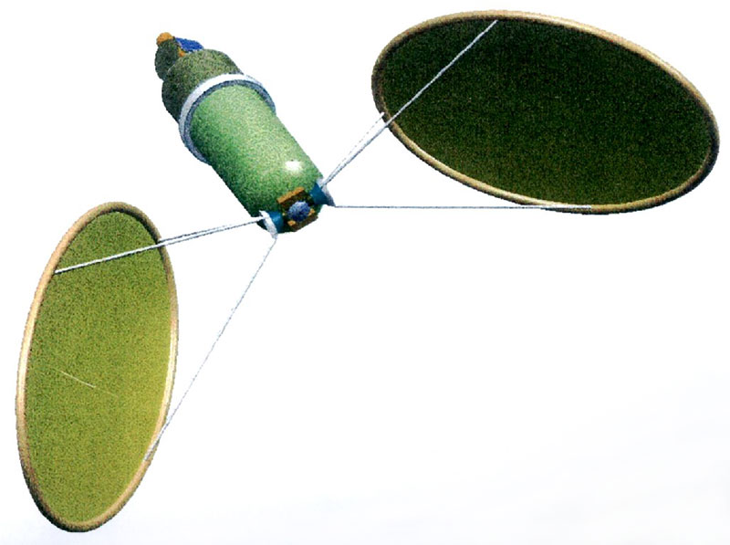
Figure 6: A LH2 solar-thermal stage featuring a pair of solar concentrators relying on inflatable collectors for the first stage, with CPC elements as second stage (EADS-ST picture).
Backbone Structures
Lightweight backbones represent the logical class for beginning the implementation of a CRES capability - which seems currently well compatible with the ESA approach. One can indeed reasonably expect that early precision structures will not depart from the backbones' technology, but rather introduce further, strong measures in design, analytical, and in-process control methodologies to achieve their functional objectives.
Of course, the advocated early morphological simplicity alone does not suffice: development objects must also show their superiority in direct comparison with other solutions. The integration of a flexible-wall element on a conventional spacecraft adds an undisputed overhead (e.g., mounting elements, protective container, pressure-control items). If the test element is "too small," this overhead becomes dominant; then, if its function is "too simple," the flexible-wall structure can no longer compete. We find this applies especially to tubes in the form of simple, cantilevered masts or booms. The element with the next degree of complexity -- an (approximately) circular frame -- seems to offer the initial solution. We refer to this class of objects (first discussed in this form by us in a 1985 paper) generically as the "Planar Instrument Carrier (PIC)" concept, whereas a toroidal structure deploys and support a flat membrane, which may be instrumented (hence the name).
While load introduction through an "end plate" seems reasonable for systems where a one can easily distinguish between a "rigid spacecraft" and its "flexible appendages," it becomes at best cumbersome when the flexible part grows to a significant size. The obvious solution is then to position the "spacecraft body" next to the center of the frame by way of a few "legs." The classical solution is given by a tripod connection, but many other possibilities obviously exist, including a monopodal one. Mastering the addition of nodes for connecting out-of-plane tubes to the torus element enables the creation of 3-dimensional assemblies, like a tripod-supported torus, to which we refer to as "single-tier structures."
The next step then will consist in adding on top of the ring a second set of legs, leading to a second toroidal ring, creating structures that extend further, and that we name two-tier objects.
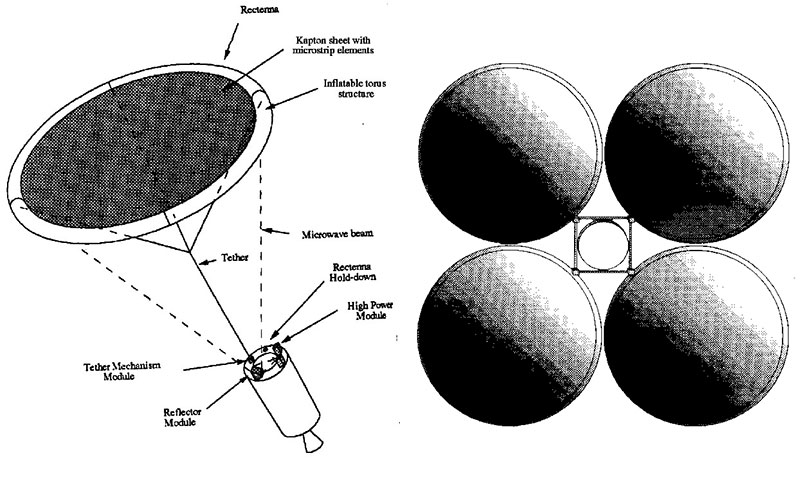
Figure 7: Frames and PICs: A torus for supporting an experimental rectenna for a European wireless power transmission experiment (Eurospace image);the concept of a solar sailing spacecraft for asteroid exploration, with four 2,500-m2 saillets.
Obviously, other, more complex truss works and skeletons (e.g. following the geometry of different polyhedra) are possible; also, CRES backbone elements can arise from architectures other than tubular skeletons.
PICs for Planar Instrument Carriers & Solar Sailing
As a CRES toroidal frame comes to replace several linear elements, frames return a better value for the investment in overhead. In addition, studies suggest that its deployment sequence can be controlled to at least a fair degree by the adoption of appropriate folding patterns. Such a design can be associated with a wide range of potential applications. While still lacking experimental objects to date, one can draw upon related experiences obtained with different items, like the FIRST shield model (see below), which used directly applicable technology for building 3.5-4 m toroidal objects, with 12 nodes; or like the stabilization tori for antenna reflectors, purely inflatable, but large (6-15 m).
In the design definition field, we started activities by reviewing (in strict collaboration with ESTEC personnel) potential applications for inflatable, space-rigidized structures. In the years since, we had the opportunity to discuss a fair number of those concepts, often in response to expressed interest of outside parties. Planar backbone structures for solar sailing have been assessed in internal studies (Fig 8), for the U3P society, as contribution to the Aurora project, as well as part of ESTEC's Daedalus study. Toroidal support structures (PIC) received attention e.g. for a power transmission rectenna (Fig 8), as well as for solar arrays employing thin-film photovoltaic (TFPV) cells. Fairly large tori (up to 100m in diameter) remain attractive for uses such as solar sailing spacecraft, of which they come to constitute the main part.
Single Tier Structures: Aerobrakes and more
Generally, single-tier objects (and the first tier of two-tiered objects) follow a pyramidal geometry, growing out of a relatively small mounting element. attachment second tier follows a prismatic cylinder layout. Single-tier elements - with different numbers of legs and various approximations to the toroid form --- can deploy lightweight aerobrakes (e.g. for lowering the initial orbit of a piggyback satellite, or to accelerate the decay from orbit of spacecraft at the end of their useful lifes), support shadow shield or "instrumented" membranes (photovoltaics, microstrip, lens or reflectarray antenna elements, sensor or multifunctional devices, etc). Our studies have shown the attractiveness of such an option for (slow) aerobraking, both in mass and economic terms.
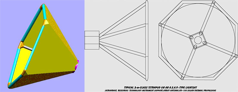
Figure 8: Single-tier skeletons, such as could be used e.g. on small satellites to form a lightweight aerobrake, or to support a reflectarray antenna or a lens collector.
Two-tier Structures: Telescopes' Tubes and Thermal Shields
The first Far Infrared Space Telescope (FIRST) proposal to ESA used an 8-m orbiting telescope, radiatively cooled to 150 K or better, thus requiring an expandable thermal shield in the 10-m size range, for which an ISRS object was suggested from the beginning. The FIRST thermal shield was conceived as a two-tier assembly, with 48 cylindrical strut elements joined at 24 nodes, half of which interfacing with four, half with three, struts. Expandable space structures of this level of complexity can serve a wide range of applications - including, in addition to telescope tubes, hangars and other unpressurized enclosures.
The two-tier structures work built upon the technological know-how acquired with the reflectors' developments, complemented by direct experimental work on 3-D thermal shield objects and, eventually, by the accumulation of design methods for a diverse range of items. Under ESTEC study contracts, work for the FIRST thermal shield culminated in the manufacture of a complete 3.5-m skeleton (Figure 9a), used for packaging, deployment, cure, and geometric check activities, and of a "full-size" connecting node (1-m diameter, with 0.45-m strut elements --Figure 9b). In their submillimetre observatories' studies, JPL adopted and consistently promoted this concept for CRES shields (Figure 10).
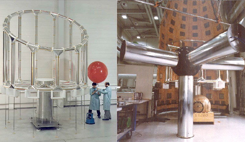
Figure 9: The 1/3-scale model of the ISRS skeleton for the FIRST'S thermal shield, and (at right), a test article of the shield's full-sized node.
In the past, NASA repeatedly referred to the potential of inflated expandable structures, in addition to supporting part of L'Garde's work. For instance, "inflatable" structures had received mention as options for solar arrays and OTV hangars in a 1984 Space Station Technology Workshop. Studies were then performed on both sort of items.
In their basic form, orbital hangars have to provide an enclosure for shielding astronauts and hardware during scheduled maintenance and repair activities, with following services: (i) controlled lighting, (ii) thermal conditioning, (iii) work stations & mounting systems, (iv) parts & tools restraint and storage, (v) a measure of micrometeoroid protection. Both pressurized and unpressurized hangar types have been studied. Thermal shields for cryogenic propulsion stages represent an additional engineering application that appears to be viable for the FIRST-shield level technology.
The use of inflatable structures to structure greenhouses, particularly operating on planetary surfaces has also been discussed.
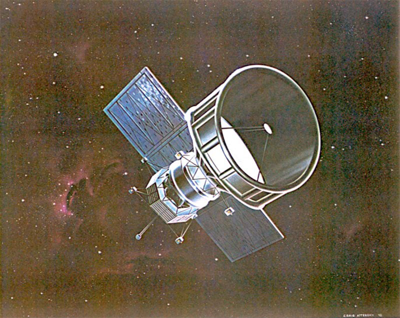
Figure 10: The ISRS shield concept applied to the proposed NASA SMILS spacecraft (JPL image).
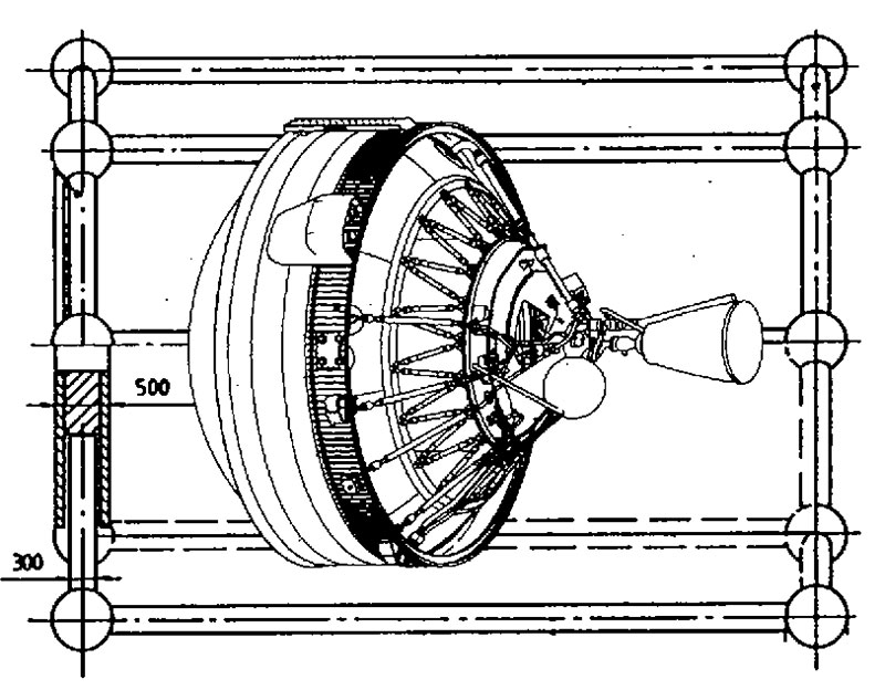
Figure 11: The ESC-B upper stage could fit inside an early ISRS two-tier demonstrator as a test example of in-orbit storage of cryogenic fluids.
We have had the opportunity to do some investigations about the use of ISRS struts as support structures for low- or moderate-gain aerials (dipoles -- Bernasconi, 1990; helices -- Bernasconi, 1991, 1998; loops -- Bernasconi, 1988; and Yagi -- Bernasconi, 1990). For electrical reasons, the feasibility could not be demonstrated; a feature common to these items' ground-use designs, consist in using a structural member as radiator, thanks to the inclusion of some crucial isolators. In those desk studies, we could not establish whether simple "air gaps" (i.e. breaks in conduction along the structure) can assure this functionality on the space structures, in particular since a proper thermal conditioning for cure calls for metallization of an ISRS cylinder. Even if, for reasons of quality and efficiency, one adds a separate rf radiator -- as a dedicated conductor mounted on the supporting tubes -- interference between the two elements may negate the antenna function.
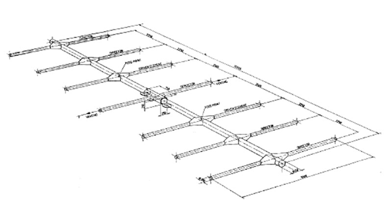
Figure 12: Concept for a 30-MFIz Yagi aerial for a Global Electrodynamics Monitor (GEM) instrument.
Multifarious Backbone Structures
We have looked further at CRES elements for realizing polyhedral skeletons and, for larger-size objects, expandable trusses, e.g. for spacious enclosures, for Fizeau interferometers (the SISTERS concept), and for Michelson interferometers.
For larger-size objects, IRSR elements can be used to realize expandable trusses (Bernasconi & Rits, 1989): empirical work has already being done at L' Garde (Guidanean & Williams, 1998). In further analogy to conventional trussworks, these designs could then be extended to penetrate additional fields, like precision backbones for reflectors (Perrygo, Cadogan & Grahne, 1999).
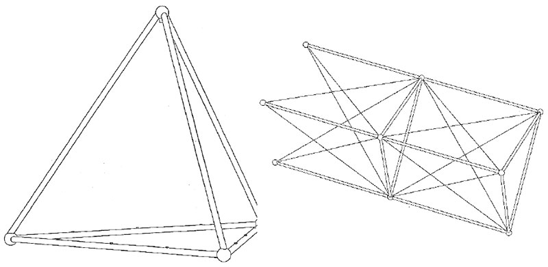
Figure 13: Very large ISRS backbone concepts: a 100-m tetrahedron, and a 1-km scaled-up linear truss.
Heavy-duty Structures for Habitation
The ASI SPES Study
The Italian Space Agency (ASI) sponsored the first major European look at the use of "Pneumatic Structures for Space Exploration -- SPeS", where Dr Bernasconi served as consultant to Oerlikon-Contraves Italiana. In addition to covering materials technology issues, he analyzed the packaging of flexible-wall habitats and had thus the opportunity to identify an interesting property of the "C-annulus" structures (a generic hybrid structures, somewhat similar in cross-section to the NASA TransHab module). From the analysis of the achievable expansion ratio -- i.e. the ratio of the volume within the expanded structure to the volume it occupies while stowed -- for different basic geometries, the torus & the C-annulus emerges as the most convenient one, achieving efficient expansion ratios already with radii only 2/3 as large as a spherical geometry would require.
On the basis of this analysis, we recommended a modified geometry of the SPeS configuration "A" habitat (Figure 14), still fitting with a 4.7-m high, 4-m diameter stowage volume but with an improved expansion ratio (5.9 instead of 4.5) and deployed volume (225 m3 vs 135).
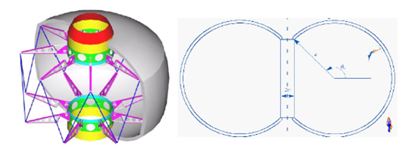
Figure 14: (a) An inflatable orbital habitat investigated during the SpeS Study (IACSA/Ing. Speranza picture),
and (b) at right, a C-annulus shell in cross section.
Space Haven Study
Flexible-wall structures enable habitats with a capacity well beyond the volumes than could otherwise find place within the transportation systems, but they pose the question of how to furnish and equip them. For this task, one can use either similarly folding elements to create secondary internal structures, or conventional, rigid, equipment that has to pass through the connections (airlocks, hatches) towards distinct carriers in a time consuming way. MCBC, as part of the HTS (Zurich) team, has addressed the type and layout of auxiliary structures that the "Space Haven" module (under study at Alenia Spazio) would need.
A One-Page Bibliography
- MC Bernasconi and GG Reibaldi (1985). Inflatable, Space-Rigidized Structures: Overview of Applications and Their Technology Impact. Paper IAF-85-210; also: Acta Astronautica 14 (1986), 455-465.
- MC Bernasconi and S Kose (1988). The Space-Rigidized Thermal Shield for the ESA Far-Infrared Space Telescope (FIRST). Paper presented at the 3rd European Symposium on Space Thermal Control and Life Support Systems, Noordwijk (NL), October 3-6; also: ESA SP-288, 165-1 73.
- MC Bernasconi and WJ Rits (1989). Inflatable Space Rigidized Support Structures for Large Spaceborne Optical Interferometer Systems. Paper IAF-89-338 presented at the 40th International Astronautical Congress, Torremolinos (Spain), October 7-13; also: Acta Astronautica 22, 145-153.
- MC Bernasconi, S Kose, and WJ Rits (1989). Optical Interferometers in Space: Configuration and Structural Concepts Using Space Rigidized Elements. Paper IAF-89-465 presented at the 40th International Astronautical Congress, Torremolinos (Spain), October 7-13; also ESA SP-303, 47-56.
- MC Bernasconi (1990). ISRS Aerials for GEM - Global Electrodynamic Monitor - Development Outline. Contraves document SN/FPP/11(90)MPL.
- MC Bernasconi (1992). The Planar Instrument Carrier Concept Applied to the Rectenna for a Power Beaming Demonstration - Powersat Study / Final Presentation by Eurospace. ESA Headquarters, 11 March. Oerlikon-Contraves Document ID-PRP/240-292/FPP.
- PY Bely, CJ Burrows, FJ Roddier, G Weigelt & MC Bernasconi (1992). SISTERS: A Space Inferometer for the Search for Terrestrial Exo-Planets by Rotation Shearing. Paper presented at the ESA Colloquium on Targets for Space Based Interferometry, Beaulieu (France), October 13-16; also: ESA SP-354, 99ff; SPIE Proceedings 1947 (1993), 73-81.
- Marco C Bernasconi & Thomas Zurbuchen (1994). Lobed Solar Sails for a Small Mission to the Asteroids. Paper IAA-L-0709 presented at the IAA International Conference on Low-Cost Planetary Missions, Laurel (MD), April 12-15; also: Acta Astronautica 35 Supplement (1995), 645-655.
- Marco C Bernasconi (1994). Design Rules for Expandable Support Structures for Near-Term, Large-Area Applications. Paper presented at the Deutscher Luft- & Raumfahrtkongress/ 1994 DGLR Annual Meeting, Erlangen (Germany), October 4-7, published in DGLR Jahrbuch 1994-I, 581-590.
- Marco C Bernasconi (1995). In_Space, Chemically Rigidizing Structures: Is Cure Through Hot Gases Feasible? Acta Astronautica 35[12], 813-816.
- Marco C Bernasconi (1997). Study of an Inflatable Space-Rigidized Support Structure for the Daedalus Solar Sail: System Design Outline. Contraves Space document SN/LIS/102(97)DER, 25 pp.
- Marco C Bernasconi (1998). Propulsive Uses of Inflatable Structures. Presentation at the Working Meeting on Low Cost Spacecraft Propulsion Technologies for Small Satellites, ESTEC (The Netherlands), 19-20 March.
- Marco C Bernasconi (1999). Space-Habitat Uses of Expandable Flexible Structures. Paper presented at the ISST'99 - International Symposium on Space Travel, Bremen (Germany), 21-23 April.
- Marco C Bernasconi (2000). Materials Aspects for Flexible-Wall Expandable Space Structures. Paper presented at the CEAS Conference on Materials for Aerospace Applications, Munich (Germany), 6-8 December; in: M Peters & WA Kaysser, Eds (2001). Advanced Aerospace Materials. DGLR, Bonn (Germany), 231-242.
- RC Parkinson, MC Bernasconi, P Bravais, & F Corberand (2001). Solar Thermal Orbit Transfer System (STOTS). Paper presented at the 52nd International Astronautical Congress, Toulouse (France), October 1-5.
- Marco C Bernasconi (2001). Inflatable Structures for Space Exploration (SPES): Stowage & Deployment Aspects. Contraves document SN/FPP/113(01)RVW, Issue A, 23 pp.
- Marco C Bernasconi & Meindert Versteeg (2004). A Review of Inflatable, Habitable Structures. Presentation at the 2nd European Workshop on Inflatable Space Structures, Tivoli (Italy), June 21-23.
- Marco C Bernasconi, Joelle Guillet, Ayodhya N Tiwari, & Axel Neisser (2004). TFPV & Gossamer Structures -- On the Way to Larger Power Generators. Paper presented at the "SPS04" Conference, Granada (Spain), June 30-July 2.
- V Peypoudat, B Defoort, D Lacour, P Brassier, O Le Couls, S Langlois, S Lienard, MC Bernasconi, & M Gotz (2005). Development of a 3.2m-long Inflatable & Rigidizable Solar Array Breadboard. Paper presented at the 6th European Conference on Spacecraft Structures, Materials & Mechanical Testing, ESTEC (The Netherlands), May 10 -12.
- B Defoort, V Peypoudat, MC Bernasconi, K Chuda, & X Coqueret (2006). Recent Advances in Rigidization of Gossamer Structures. In: In: Eugenio Onate & Bern Kroplin (Eds). Recent Advances in Textile Membranes & Inflatable Structures. Computational Methods in Applied Sciences 3, 259-283. Springer (Dordrecht, NL) and ECCOMAS.
- Marco C Bernasconi (2008). On an Economic Approach to the Development of Flexible-Wall Shelters for Space Exploration & Utilization. Acta Astronautica 63[04], 682-686.
ISRS-Related Contracts at Contraves Space
| Study of Large, Ultra Light, Long Life Structures in Space - Phase I | 1978-1979 |
| Study of Large, Ultra-Light, Long Life Structures in Space: Phase II | 1979-1982 |
| Study of Large, Ultra-Light, Long Life Structures in Space: Intermediate Phase (IIc) | 1982-1983 |
| An Inflatable Space Rigidized Reflector for QUASAT - Feasibility Study | 1984 |
| Inflatable Space Rigidized Antenna Reflector Structure Technology - Phase III | 1984-1988 |
| FIRST Inflatable Thermal Shield - Phase 1 | 1985-1987 |
| Flight Experiment of a LOAD-3 Assembly - Development Study | 1985-1988 |
| An Inflatable Space Rigidized Reflector for QUASAT - Phase 2 | 1985-1988 |
| Heterodyne Spectroscopy Study - Thermal Shield Adaptation to New Orbit Conditions | 1986 |
| The Technology of Inflatable Space Rigidized Antenna Reflectors - Phase 4A: Design, Manufacture & Test of a 10-m Aperture ISRS Reflector |
1986-1990 |
| An ISRS Reflector for QUASAT - Phase 3: Manufacture & Test of a 6-m Reflector | 1986-1990 |
| Very Large ISRS Struts - Feasibility Study | 1986-1990 |
| FIRST Inflatable Thermal Shield - Phase 2 | 1987-1988 |
| An ISRS Reflector for Quasat: Consultancy to Quasat Phase A | 1988 |
| The Technology of ISRS - PSDE SAT2: L-Band Antenna Reflector System Study | 1989 |
| FIRST Inflatable Thermal Shield - Phase 3 | 1989-1990 |
| Dynamics of Large Reflectors - Dynamic Analysis Study for an ISRS Reflector | 1989-1991 |
| FIRST System Definition Study - Study Report on Thermal Shield | 1990 |
| Inflatable Space Rigidized Structure Boom Experiment - IBEX | 1990 |
| The Technology of ISRS - Long Term Material Testing | 1990-1992 |
| The Technology of ISRS - In-Orbit Cure Experiment (ICE-1) | 1990-1997 |
| Solar Sailing Study. In collaboration with the Berne University's Physics Institute | 1992-1993 |
| Study of an Inflatable Space-Rigidized Support Structure for the Daedalus Solar Sail | 1997 |
| Study of ISRS Elements for Lightsats | 1998-1999 |
| System Study of Current Applications for Inflatable Space-Rigidized Structures | 1999-2001 |
| Solar-Thermal Upper Stage Technologies for Future Launcher Generations Study | 1999-2001 |
| SPeS - Pneumatic Structures for Space Exploration | 2001 |
| Thin-Film Solar-Cells Arrays Study - Phase 1 | 2001-2003 |
| IFES Membrane Antenna --- Inflatable Superstructure Feasibility Study | 2002 |
PICTURE CREDITS
The credits follow the figure number, separated by commas when more than one picture appear from left to right.
Cover, 10: NASA (1992). 0, 7, 8, 11, 14: Author (2004, 1995, 1996, 2001, 2004). 1, 3, 5, 9, 12, 13: Contraves AG (1984, 1990, 1988, 1990, 1992, 1990). 2: CSELT (1986). 2, 4: ESTEC (1986, 1985). 6: EADS-ST (2001). 7: Eurospace (1992). 14: Ing. Speranza (2001).
NOTICE: This page contains copyrighted material the use of which has not always been specifically authorized by the copyright owner. Such material is made available in an effort to advance understanding of political, economic, and scientific issues, etc., in the belief that this constitutes a 'fair use.'
CRES & Related Contracts let to MCB Consultants
| Customer | Period | |
| Review of Rigidization Technologies for Gossamer Structures | ADS-LV | 2002 |
| Technology Assessment of Circular Ring Structures for Deployment in Orbit |
OURS Foundation | 2003 |
| Verification Issues for Flexible-Wall Expandable Structures | ESTEC | 2003 |
| Review of Thin Membranes' Materials | ESTEC | 2003 |
| Consultancy: Validation & Qualification Logic for Inflatable Technologies |
EADS-LV | 2003 |
| Structural Design of Advanced Solar Arrays | EADS-ST | 2003-2004 |
| Consultancy: YES2 AIR | Delta-Utec | 2003 |
| Consultancy: Manufacturing of CRES Cylinders | Astrium sas | 2004 |
| Auxiliary Structures for the Space Haven Inflatable Habitat | HTS | 2004-2005 |
| Consultancy: EAP Applications | HPS | 2004-2005 |
| Ultralight Structures | EADS-ST | 2005-2008 |
| Polymerisation of composite structures in free-space conditions | EADS-ST | 2005-2006 |
| Consultancy: Low-mass solar arrays for small, planetary-surface payloads |
(DLR) | 2004, 2007 |
Contact:
MC Bernasconi Consultants
CH-8953 Dietikon
Switzerland
Fax: +41 44 741 1597
Request technical brochures, by writing to: gordon@bathome.org
See also:
Inflatable Technologies for Sculpture in Earth Orbit